Using the ATmega8 Series Microcontrollers
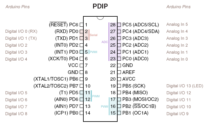
Should work with ATmega48, ATmega88, and ATmega168 Microcontrollers. Assuming the use of a 28-pin PDIP package.
Tested and verified with an ATmega168.
Total cost: at least $2.76, at most $12.70
1x
|
Sparkfun |
Goldmine | ATmegaXXX Microcontroller ($1.50 - $5.00)
1x
|
Sparkfun |
Goldmine | SPST momentary normally-open type switch ($0.10 - $0.50)
When ordering online, Goldmine Electronics is often much cheaper than Sparkfun, and sells in large quantities. Sparkfun has one LED for $0.50, where Goldmine has nearly identical LEDs, in a package of 25, for $0.99. On the other hand, Sparkfun generally has more "high-tech" items, and stocks tons of great things for prototyping and tinkering.
The 7805 has an input voltage range of +5V to +28V
The 7805's maximum current rating is 1 Amp
The 7805 may require a heatsink if it is driving a high load or having trouble regulating the input voltage.
The 100uF capacitor from Sparkfun is rated at 25V, so limit the 7805's input voltage to around 12V.
Better yet, just limit the 7805's input voltage to about 9V.
C .... Capacitor
R .... Resistor
S .... Switch
Q .... Crystal
D .... Diode / Light-Emitting Diode
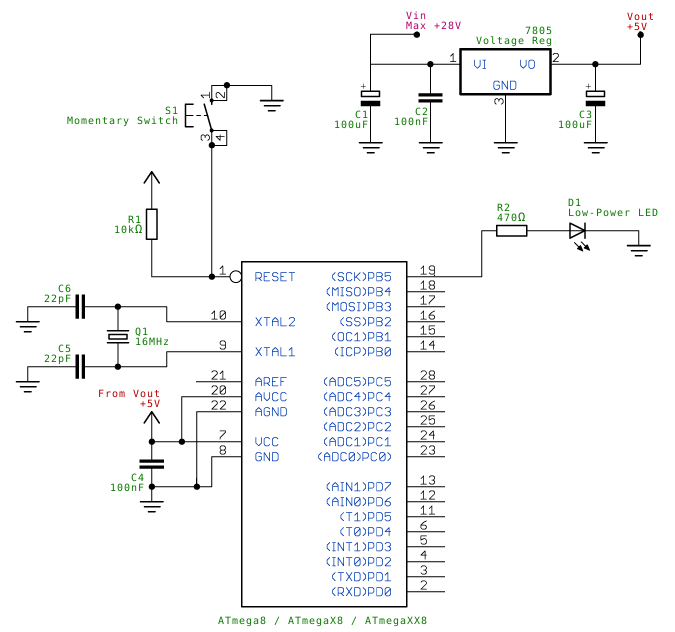
Each 22pF capacitor goes between ground and one of the 16MHz oscillator pins
The 16MHz oscillator connects to Pin 10 and Pin 9 (XTAL2 and XTAL1) on the ATmegaXXX Microcontroller
The 10000 ohm resistor goes between +5v and Pin 1 (RESET) on the ATmegaXXX Microcontroller
The SPST switch goes between ground and Pin 1 (RESET) on the ATmegaXXX Microcontroller
One 100nF capacitor sits between Pin 7 (VCC) and Pin 8 (GND) on the ATmegaXXX Microcontroller
The same 100nF capacitor also sits between Pin 20 (AVCC) and Pin 22 (AGND) on the ATmegaXXX Microcontroller
One 100nF capacitor sits between +Vin and GND on the 7805
One 100uF capacitor sits between +Vin and GND on the 7805
The other 100uF capacitor sits between +Vout and GND on the 7805
If you're like me, you'd like to program your microcontroller using the most high-level language possible. Discouragingly, most microcontrollers are typically programmed using ASM. No fun.
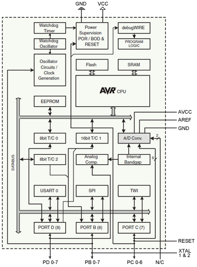
The ATmega series of microcontrollers belongs to the
AVR family, created by Atmel. Fortunately for us, all AVR microcontrollers can be programmed with C and C++. A widely available version of GCC exists for AVR microcontrollers, called
AVR-GCC.
Once you have compiled your C or C++ program into an AVR binary using AVR-GCC, you will need to "burn" it to the chip itself. This can be done with one of three applications:
AVRDUDE,
UISP, or
AVR Studio.In order to actually get one of those applications talking to your chip, you will need hardware to plug the chip into your computer. There are five pins on the chip for something called an In-System Programmer, or ISP for short. These pins are used by your computer to program the chip.
A common piece of hardware for connecting these ISP pins to one of your PC's USB ports is the
AVRISP mkII. These usually sell for $25 to $30, and are one of the easiest programmers to use. If you don't feel like going for one of those, you can also build your own Parallel Port ISP programmer without trouble. There are a number of designs for a parallel programmer,
but this is the simplest.
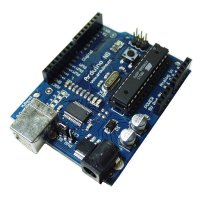
Arduino is an AVR-based prototyping board with an emphasis on ease of use. It has breakout headers for I/O pins and power. It also features a USB interface using the FT232RL chip, which allows RS232 serial communication through a USB device, eliminating the need for a separate AVR programmer. The Arduino project also has an Integrated Development Environment for writing AVR code in a C/C++-derived language called Wiring. The IDE also includes many helpful libraries and a nice function framework. Check out the
Arduino website!
The Arduino bootloader will flash Pin 19 (PB5) twice on a 500ms interval at boot-up. The low-power LED is meant for this, or for your own software's status monitor. Use the 470 ohm resistor in series with the LED.
ATmega chips programmed by the Arduino will work as stand-alone microcontrollers. However, in order to use a new ATmega with the Arduino, you must write the Arduino bootloader to the ATmega chip. This can be done with
AVRDUDE,
UISP, or
AVR Studio. See the "Programming your ATmega Chip" section above.
ATmega chips running the Arduino bootloader will have a 5 second delay at startup. This is where the bootloader listens for serial data from the Arduino programming environment.
If the chip flashes the LED on Pin 13, but never starts executing your code, then place a 10000 ohm resistor between Pin 2 and Pin 3. The bootloader may "wait" forever because it mistakes noise for data on those pins.
There are three main I/O ports: Port B (PBx), Port C (PCx), and port D (PDx)
Port B interfaces with the SPI module. It has 8 I/O pins. Port B also supports pin change interrupts, and can be used for timing using the ICP1 pin.
Port C interfaces with the TWI (2-Wire or I²C) module, and provides 6 ADC inputs by interfacing with the A/D Converter module. Port C has 7 I/O pins, and supports pin change interrupts. Analog inputs are on pins PC0 through PC5
Port D interfaces with the chip's USART (UART) module. It can also function as an analog comparator on pins PD6 and PD7.
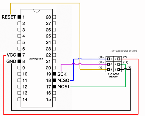
Pin 16 (PB2) is SS (Slave Select)
Pin 17 (PB3) is MOSI (Master Output, Slave Input)
Pin 18 (PB4) is MISO (Master Input, Slave Output)
Pin 19 (PB5) is SCK (Serial ClocK)
Pin 27 (PC4) is SDA (Serial DAta)
Pin 28 (PC5) is SCL (Serial CLock)
Pin 2 is Serial RX (PD0)
Pin 3 is Serial TX (PD1)
Pin 6 is Serial Clock (PD4)
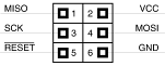
ICSP Header Pin 1 goes to MISO
ICSP Header Pin 2 goes to +5V
ICSP Header Pin 3 goes to SCK
ICSP Header Pin 4 goes to MOSI
ICSP Header Pin 5 goes to RESET
ICSP Header Pin 6 goes to ground
2x3 ICSP Header:
Hook-Up Diagram:
 |
|  |
|  |
|  |
|  |
|  |
|  |
|  |
|